Gas Chromatograph (GC) and GC5 interface
GC, GC5 and isoprime visION
The GC / GC5 system, when coupled with the isoprime visION is designed to determine the composition of individual compounds in complex organic mixtures.
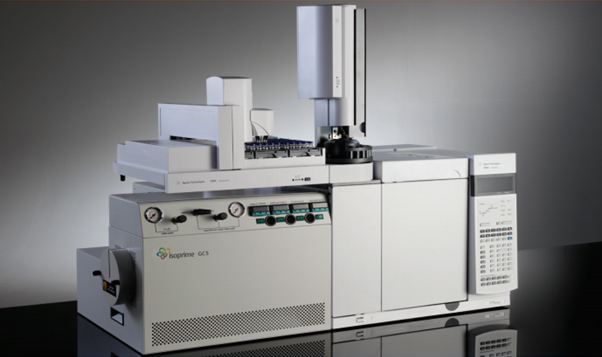
Figure 4-11: GC coupled to a GC5
The organic compounds are separated using a GC. Chosen portions of the chromatogram are diverted to a combustion / pyrolysis interface where they are oxidized / pyrolised to produce analytes that can be measured using the isoprime visION.
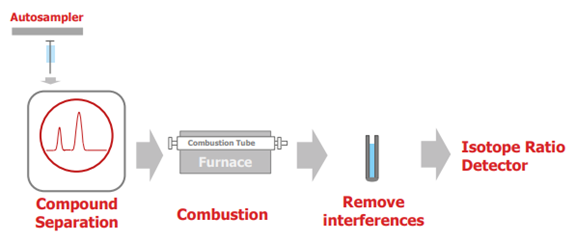
Figure 4-12: Sample flow through the GC, GC5 and IRMS
The remainder of the chromatogram is diverted to the GC Flame Ionization Detector (FID) (or other GC detector).
Provided conversion to the gaseous analyte is complete and that no contamination or isotopic fractionation is allowed to occur anywhere within the preparation system, then the analyte produced from an organic material has an isotopic composition that is totally representative of that material.
The complete GC GC5 Interface consists of the following parts:
- A Gas Chromatograph (Agilent 7890B), modified for IRMS coupling
- The combustion / pyrolysis GC5 Interface, including regeneration possibilities for the reactor tubes.
Agilent 7890 GC
An Agilent 7890 GC User Manual is supplied with the instrument.
In a standard configuration, the Gas Chromatograph comprises of a standard GC oven, an injector (e.g. split / splitless), a GC column for separation and a detector (e.g. flame ionization detector, FID). However, to facilitate compound-specific stable isotope measurements, it is necessary to modify the GC, this involves interfacing it to the GC5 and also introducing a heart split mechanism. With these modifications, however, it is still possible to use the GC as a stand-alone unit if the appropriate Agilent software has been provided.
Split / splitless injector
As standard, each Gas Chromatograph is fitted with a split / splitless injector and can be operated in both split and splitless modes. More information can be obtained from the Agilent 7890 GC user manual.
The injector comprises of a heated chamber, an injector liner, an inert gold-plated seal, a septum, a helium carrier gas inlet, a split vent valve and a septum purge vent. The GC column (or pre-column) is connected to the bottom of the injector using a nut and a graphite ferrule (GFF 16-005) through the gold-plated seal and into the injector liner. The column should protrude between 4 and 6 mm above the graphite ferrule.
In split injection mode, the sample is introduced into the injector using a syringe, where it is vaporized and a proportion of the sample gas is passed onto the GC column while the rest is diverted through the split vent. This is in contrast to splitless mode where the split vent is closed during injection and for a set period of time (sample purge time, ~ 0.75 to 1 min) where the sample is transferred onto the GC column. After the sample purge time has elapsed the split vent would then open again. The septum purge flow is common in both modes and consists of a small flow of helium (~3 ml/min) under the septum to prevent any bleed from the septum entering the column.
The desired injection program, including injector temperature, split ratios and sample purge times can be programmed using the GC keypad or directly using IonOS.
An advantage of using the injector in split mode is that it does the dilution of your sample rather than the analyst diluting manually with varying volumes of solvent. Also, compared to splitless injections you often see better chromatography due to less solvent being transferred onto the column and an increased flow resulting in better focusing of the solvent / analytes. Again as a result of the faster transfer time onto the column, if the sample is susceptible to thermal degradation it would be advantageous to operate the injector in split mode, although other injectors maybe be even more suitable, e.g. cold-on-column (COC).
In splitless mode, the longer time to transfer onto the GC column gives rise to potential peak broadening, this however is minimized by ensuring the boiling point of the solvent used to dilute the sample is less than the starting GC oven temperature. For example, a GC oven temperature of 50°C would be recommended when hexane (BP 69C) is used as a solvent. With this technique you are able to focus the solvent / analyte as a narrow band on the front of the column. This is more crucial in splitless mode, however this practice is also encouraged in split mode.
It is important to consider the solvent being used and its vapour expansion volume when analyzing in either split or splitless modes. When injecting a certain volume of solvent into the injection port, the solvent will expand when converting into the vapour phase – this volume must not be greater than volume of the injector liner otherwise ‘backflash’ can occur resulting in carryover and poor reproducibility. The vapour expansion volume is dependent on the actual solvent used, the injector temperature and the inlet pressure. Listed below are resultant vapour volumes from four example solvents (Table 4-2). Out of the four, Hexane and Acetone would be safe to use, methanol with caution and only ~0.5ul of water could be used as the expansion volume is greater than the liner volume. Please note that water has other characteristics that also make it a less desirable solvent to use.
Table 4-2: Examples of solvent expansion volumes
|
Solvent |
Inj vol (ul) |
Injector temp (C) |
Inlet pressure (psig) |
Volume of liner (ul) |
Vapor volume (ul) |
|---|---|---|---|---|---|
|
Hexane |
1 |
250 |
10 |
1000 |
196 |
|
Acetone |
1 |
250 |
10 |
1000 |
347 |
|
Methanol |
1 |
250 |
10 |
1000 |
631 |
|
Water |
1 |
250 |
10 |
1000 |
1414 |
Options to use other injectors are also available, e.g. Cold-on-column (COC), Programmable Temperature vaporization (PTV), multi-mode injector (MMI), etc.
GC Column
The GC5 comes with two different GC columns: i) HP-5 and ii) HP-Plot/Q.
The HP-5 is a wall coated open tubular (WCOT) column and comprises of a fused silica column with a liquid film stationary phase coating the inner wall and a polyimide protective outer layer; the stationary phase (5% Diphenyl/95% dimethyl polysiloxane) is relatively non-polar and versatile.
For the analysis of gas mixtures, the HP-Plot Q column is provided. This differs slightly to the HP-5 in that it is a porous layer open tubular (PLOT) column and the stationary phase is a solid substrate (polystyrene-divinylbenzene); this column is particularly good at separating C1 to C3 alkanes.
Typically columns used in IRMS applications have lengths ranging from 20 to 60 m, internal diameters from 0.200 to 0.320 mm (‘narrow’ to ‘wide’ bore) and in the case of WCOT columns, have stationary phases with a film thickness of less than 0.5um (a wide range of polarity and selectivity options are available).
Briefly, a GC column with a long length sees the sample analyte interacting with the stationary phase for longer and hence increases the retention times and thus improves peak separation; however, peak widths will be broader than those observed in shorter columns and the analysis time will be longer. Columns with thicker stationary phases allow more sample to be loaded onto the column and, similar to an increase in the length, results in longer retention times. Good peak resolution of low molecular weight compounds can best be achieved with a thick stationary phase, while resolution of high molecular weight compounds is better when the stationary film is thinner. Another characteristic of a thicker stationary phase is that column ‘bleed’ will be higher.
When the sample analytes have a similar polarity to the stationary phase or the phase has a strong selectivity there will be a greater interaction which improves peak resolution. Our partner, Agilent provides a wide range of GC columns with varying polarities and selectivities covering many different application areas. For further information, please refer to the Agilent J&W GC Column Selection Guide:
https://www.agilent.com/cs/library/catalogs/Public/5990-9867EN_GC_CSG.pdf
Flame Ionization Detector (FID)
Each Gas Chromatograph is fitted with a Flame Ionization Detector (FID) which detects most organic compounds combusting them within a hydrogen and air environment. This is not an essential component in compound-specific stable isotope analysis using GC, but it can be useful in determining solvent retention times and diagnostic troubleshooting
More information can be obtained from the Agilent 7890 GC user manual.
Heart Split mechanism
The heart split mechanism operates via a combination of both a mechanical input (heart split valve) and a back flow of pressure. Its purposes are to:
- Prevent solvent from eluting through the furnace tube towards the IRMS by diverting the flow towards the FID. Solvent passing through the furnace is undesirable as, depending on the volume, it will have an adverse effect on the furnace tube chemistry. In the case of GC combustion modes, solvent would severely deplete the furnace tube’s oxidation capacity; this would be particularly evident when injecting samples in splitless mode or using a COC injector when the volume of solvent injected is larger.
- Enable individual chromatographic peaks or groups of peaks to be ‘Heart Cut’ from a complex chromatogram so that they can be selectively diverted to the furnace / isoprime visION Mass Spectrometer.
- Enable the introduction of pulses of monitoring gas onto a clean backgrounds by diverting the GC column effluent away from the furnace / isoprime visION Mass Spectrometer.
A schematic of the GC oven arrangement with heart split mechanism is shown in Figure 4-13.

Figure 4-13: Heart split mechanism. Deactivated fused silica is used to link the splitter union to the furnace tube, the splitter union to the heart split valve and the heart split valve to the FID (internal diameters indicated). Labels A to E indicate which ferrules are used (Table 4-3).
Table 4-3: Ferrules used in GC oven arrangement
|
|
Ferrule |
Description |
|---|---|---|
|
A |
GVF 16-003/004 |
85% Vespel ‘Backdrilled’ |
|
B |
GVF 16-005 |
85% Vespel |
|
C |
GVF 16-16 |
85% Vespel Sealing Ring |
|
D |
GFF 16-005 |
Graphite |
|
E |
GVF 16 (2) 004 |
85% Vespel Two Hole |
|
F |
1/4" Vespel |
100% Vespel |
Three sources of helium are involved in the heart split mechanism, these are: i) carrier gas helium which enters the GC column through the injector, ii) helium entering the furnace tube at the zero dead volume fitting at the end of the furnace tube (sample line helium), and iii) FID helium that enters the heart split valve on route to the FID.
When the heart split valve is open, the carrier gas helium enters the splitter union (VSOS), and complimented by the sample line helium pressure, travels the path of least resistance towards the heart split valve and hence to the FID. With the heart split valve is closed, the GC flow is prevented from passing through the heart split valve towards the FID. In this situation, the pressure at the splitter union increases to a level greater than the sample line helium pressure and diverts the GC flow through the furnace tube.
Splitter union (VSOS)
The VSOS is a zero volume connector that is used to split the GC column flow by diverting the sample to either the FID or furnace tube fitting (Figure 4-14).
Two deactivated fused silica capillaries (250um ID) are connected to one end of the splitter union using a 2-hole 85% Vespel/15% graphite ferrule (GVF 16(2)-004). The silica capillaries should not protrude through the ferrule, but instead level with the base of the ferrule or pulled back slightly (~1mm). The GC column is fed through the union and is connected using a 85% Vespel ferrule (GVF 16-004); its position should be level with the end of the union or pulled back slightly (~1mm).
When connecting the VSOS union it is recommended to connect the two silica capillaries first by holding the nut fixed and rotating the VSOS union to tighten it onto the nut. This way the silica won’t twist together and possibly break. Care should be taken to not over-tighten connections as the silica capillaries and/or the GC column could be crushed and potentially block the union.

Heart Split Valve
The heart split valve comprises of a modified MOVPT valve (SGE) where the on / off function is actuated pneumatically.
The heart split valve is connected to the FID via a length of fused silica capillary (~25cm, 320um ID). A 85% Vespel/15% graphite ferrule is used to connect the capillary to a side connection of the valve and graphite ferrule (GFF 16-005) to the FID. The other side connection of the valve is where the FID helium is introduced.
The ferrule required for the bottom connection of heart split valve is a special “backdrilled” one, where the hole is a different size at each end (GVF 16-003/004). The silica capillary (~30cm, 250um) from the VSOS splitter is connect here, but only fits half way through the ferrule; this is so that needle in the heart split does not damage the capillary when the heart split valve is closed (Figure 4-15). It is essential the outer diameter of the capillary is large enough that it does not pass all the way through the ferrule.

The GC5 Interface
The main function of the GC5 interface is to enable complete conversion of components eluting from the GC column into target gases that are suitable for analysis by IRMS, e.g. GC-C (CO2), GC-N (N2), GC-H (H2) and GC-O (CO). To facilitate this conversation, the GC5 interface controls and distributes the gas flows and regulates the temperatures to the interface heater and furnace.
Gas control and distribution
An illustration of the gas lines within in the standard GC5 interface are displayed in Figure 4-16
As indicated in Figure 4-16, helium and oxygen are all introduced into the unit at the rear. The helium is distributed to supply the furnace tube (i.e. sample line helium) and the FID, the oxygen is used to oxidize or regenerate the furnace tube (GC-C and GC-N only), while the helium line is used to actuate the heart split valve within the GC oven and the MOVPT valve that allows oxygen to be bled into the sample line helium flow.

On the front panel of the unit there are two 10 psi pressure regulators, one to control the sample line helium supply and the other for the FID helium. Between the pressure regulators there is a manual switch valve indicating a ‘left’ or ‘right’ channel for the sample line helium; for GC-C, GC-N and GC-H this should be point to the ‘right’. The GC5 can be upgraded to incorporate a GC-O configuration, here the ‘left’ is normally selected.
The sample line helium flows from the pressure regulator to a connection beneath the T-section of MOVPT valve and towards the zero dead volume connector at the end of the furnace tube (‘GC oven side’). From here the helium flows through the furnace tube, but also plays a crucial role in diverting GC flow away (i.e. the heart split mechanism). The sample line helium pressure should be set between 2 and 3 psi.
The FID helium travels from the pressure regulator towards one of the side connections of the heart split valve in the GC oven. The other side connection is connected to the FID itself. The FID helium pressure should be set to approximately 0.3 psi.
The O2 gas, which is used to oxidize the furnace tube, first flows through a metering valve, and from here it then transverses the T-section of the MOVPT valve towards a vent on the side of the GC5 unit. The flow of O2 is controlled by adjusting the metering valve and can be measured by connecting a flow meter to the vent. When the MOVPT valve is closed, the O2 is prevented from bleeding into the sample line helium flow, i.e. similar to the heart split valve in the GC where the needle of the MOVPT valve blocks the special ‘back-drilled’ ferrule (Figure 4-15). By actuating a solenoid valve at the rear of the unit, helium can open the MOVPT valve and allow the O2 to mix with the sample line helium, which is introduced beneath the ferrule. Further information on how to oxidize and regenerate a furnace can be found in Furnace tube oxidation strategies.
Heated zones
The GC5 interface comprises of two temperature controlled heated zones. These being, i) an interface heater that is positioned between the GC and the furnace assembly and ii) the furnace assembly itself.
Interface heater
An interface heater is necessary to ensure that sample components eluting from the GC column are fully transferred to the furnace tube without risk of condensation.
The temperature of the heater must be sufficiently high to eliminate any cold spots in the sample pathway from the end of the GC column to the furnace tube. If not, the less volatile components may condense which will adversely affect their chromatographic peak shape (e.g. tailing) and measured isotopic ratios.
The interface temperature can be controlled directly with our software, IonOS or via the CAL3300 controller situated on the front panel of the GC5 interface. For normal operation, the interface temperature is set to 350°C.
Furnace assembly
The furnace assembly comprises of a high temperature furnace (up to 1500°C) that is controlled by a CAL3300 controller on the front of the GC5 interface or directly using IonOS.
A micro-bore quartz or ceramic furnace tube runs through the center of both the interface heater and furnace. In the GC oven, the front end of the furnace tube is connected to the sample line helium input and a capillary from the VSOS splitting union (Splitter union (VSOS). The other end of the furnace tube exits the furnace and is connected to fitting with an open split and a fused silica capillary taking sample flow towards the IRMS.
Furnace tube
The furnace tubes used in the GC5 interface are, depending on the application, either quartz or ceramic (600mm length).
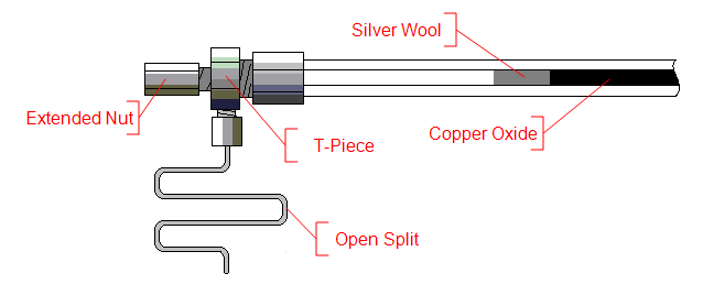
When installing a furnace tube it should be slid carefully into the furnace from the exit side. Most tubes can be installed in any direction, but in the case of the ‘high capacity’ GC-C option the silver wool should sit at the GC5 exit end (Figure 4-17).
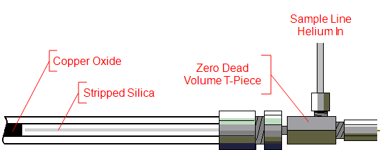
Before the inserting the furnace tube into the furnace it is recommended that the fittings should be connected to the exit end of the furnace tube first. The fittings required for the both GC-C (high capacity) and GC-C (natural gas) consist of an extended nut, T-piece with nut, a graphite ferrule (GFF 4-4) and stainless steel line (15cm, 0.006” ID) that is connected to the vent (Figure 4-18). This vent is important for stable analysis and is known as the ‘open-split’ .
Once the furnace tube is in place, the GC side fittings require to be constructed in situ (Figure 4-19). A zero dead volume T-piece assembly is connected to the front end of the furnace tube using a nut and Vespel ferrule (GVF 4-4) and the sample line helium using a nut and Vespel sealing ring (GVSR 16-16). The length of deactivated fused silica (~50cm, 250um ID) from the VSOS splitter union is then inserted into furnace tube through the T-piece assembly. Please note that the polyimide outer coating should be removed from approximately 10cm of the end of the column entering the furnace tube by first burning under a flame.
Furnace tube configurations for the PetrovisION System
The PetrovisION System is provided with three different furnace tube options:
- GC-C (high capacity)
- GC-C (natural gas)
- GC-H (high temperature)
GC-N, GC-H (low temperature) and GC-O furnace tube options are also available.
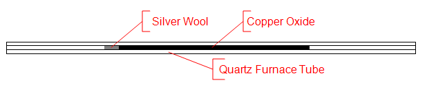
GC-C (high capacity)
The GC-C (‘high capacity’) furnace tube comprises of a quartz furnace tube, with 200 mm of copper oxide in the center and a 20mm of silver wool plug after the copper oxide. The copper oxide aids the combustion of the organic compounds to CO2 and the silver wool acts to bind any halogens.
This furnace tube configuration with its high oxidation capacity is used for nearly all GC-C applications.
The furnace is operated with a temperature of 850°C.
GC-C (natural gas)
An optimized GC-C packing is necessary to be able to more efficiently combust methane. The furnace tube is the same as the ‘high capacity’ equivalent, except the copper oxide packing is replaced with Nichrome, copper and platinum wires. The wires require oxidation prior to analysis.
The ‘natural gas’ configuration can be used for all GC-C applications, however it has a much lower oxidation capacity than the ‘high capacity’ option.
The furnace is operated with a temperature of 950°C.
GC-H (high temperature)
A high temperature GC-H configuration is required for natural gas analysis due to the high energy requirement to be able to convert methane to H2 gas. The furnace tube comprises of ceramic tube that is simply conditioned with a layer of carbon prior to use.
The ‘high temperature’ GC-H option can be used for most GC-H applications, except where the target molecules contain nitrogen or halogens. Nitrogen and/or halogen containing organic molecules can be analyzed using the ‘low temperature’ furnace tube option.
The furnace is operated with a temperature of 1450°C.
Table 4-4: Summary of GC Furnace tube configurations
|
GC configuration |
Furnace tube / Packing / Temperature |
Description |
|---|---|---|
|
Quartz / Copper Oxide / 850°C |
High Capacity All applications except natural gas |
|
Quartz / NiChrome, Copper, Platinum / 950°C |
Natural Gas option Suitable for all GC-C applications, but with lower capacity |
|
Quartz / Chromium / 1050°C |
All applications except natural gas analysis Suitable for N-containing compounds |
|
Ceramic / Empty / 1450°C |
Natural Gas option Suitable for most GC-H applications except N containing and halogenated compounds |
|
Quartz / NiChrome, Copper, Platinum / 950°C |
A one furnace tube solution Oxidation requires careful optimization |
|
Ceramic / Nickel tube / 1250°C |
Suitable for all GC-O applications except N containing compounds |
Open split
The open split assembly is designed to protect the ion source from pressure fluctuations arising from the operation of the GC or GC5 interface, with the pressure at the open split being maintained by ambient atmospheric pressure. The open split marks the change from a high pressure system in the GC and combustion interface, to a low pressure system dominated by the IRMS vacuum system.
GC carrier and sample line helium flows into the GC end of the furnace tube via a zero dead-volume T-Piece towards the open split. At the open split a fused silica capillary is connected to the isoprime visION Mass Spectrometer, where the vacuum system draws in the required helium. Excess helium, not transferred to the isoprime visION Mass Spectrometer, is vented to atmosphere through the stainless steel capillary on the open split union.